For my 144 MHz PA, I wanted to have a separate power meter to monitor outgoing power. Off course I could have bought a BIRD with all slugs but building one yourself gives a more satisfied feeling.
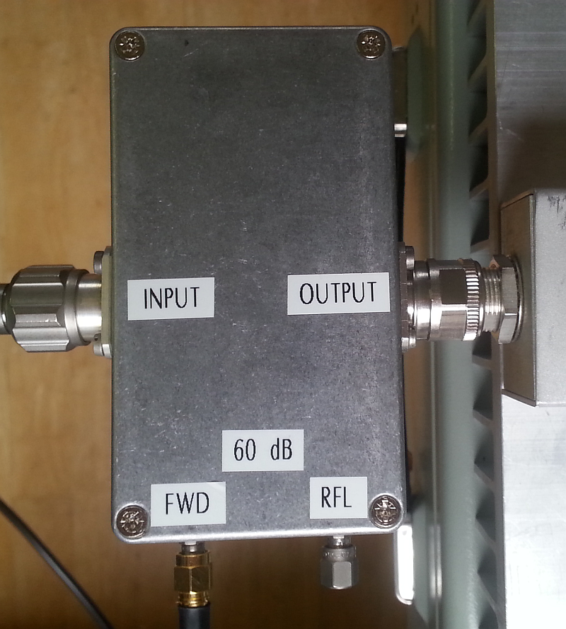
Since my PA can produce ~800 Watt, I needed something what could measure this without problems. I decided to use a coupler that has a attenuation of 60 dB for both forward and reflected power.
The design is done using a RF-detector and ARDUINO NANO for simple math and meter control.
To ‘downconvert’ the QRO power, I used a coupler designed by W1GHZ, detailed information can be found here (pdf alert). With some minor tweaking and the use of a VNA I was able to get an exact attenuation of 60 dB, W1GHZ describes in his article how to do this.
As for the detector the famous AD8307 was used, this is a cheap and easy to get part. Gives a db-linear analog output of appr. 25 mV/dB. The output of the AD8307 is multiplied by two to have a better use of the AD input of the ARDUINO. According to the datasheet, the output is appr. 2V with 0 dBm input, multiplied by two gives appr. 4V out which can handled by the ADC converter ( 0- 5 V ) .
Since the coupler has a fwd coupling of 60 dB, the maximum expected input power (with a 1 kW amplifier) is 0 dBm.
Calibration is done at 0 dBm only, linearity (25 mV/dB) is taken from the datasheet and not calibrated since measurements showed it was more then accurate enough for my application.
The ARDUINO does the AD conversion, reads the switches and controls the meter using PWM.

A feature is the NOR and AVG meter switch: in the NOR setting the meter follows the input directly and the AVG setting averages the input signal over 0.6 seconds using a moving average method.
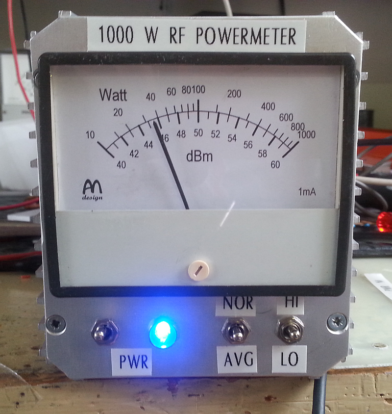
The ARDUINO also ‘maps’ the AD data to the meter, this way we can make multiple ranges but for my application two ranges were more then enough. The HI range is from 10W to 1000W and the LO range is from 0.1W to 10W. The meter has a printed scale only for the HI range, if LO range is used, user must do the simple math himself.
At powerup the LED flashes for about 2.5 seconds, during this period the meter goes from left to right. If during this period the Mode switch is toggled, the unit goes into calibration mode. User must supply 0 dBm at 144 MHz (or any other freq within AD8307 range) and at the same time the meter can be calibrated at full scale using the internal potmeter (see schematic). After this the Mode switch can be toggled again and the calibration factor (for 0 dBm) is stored into EEPROM. Everytime the PowerMeter starts, this value is read and used as a reference.

Schematics can be found here PowerMeter Schematic V1.0 (pdf alert), if you want to have the code (no warranty), please send me an email at pa3bwe at amsat dot org.
Scale on analog mA meter has been designed using Meter software from Tonne Software.