Many people use dummyloads to ‘dump’ the RF power when testing their circuits. If you want to know how much power is dumped into the load you can measure this by switching a coupler in series. This will measure the forward and reflected power. Assuming the load is 50 ohm, the reflected power will be very low and therefore not of interest.
Another approach is to use an attenuator: this usually has an in- and output. If they are reversed, the attenuator will most likely not survive, specially with high power levels. This has to do with the fact that most of them have a tapered input and the first stage only attenuates (example) 1 db, second stage 2dB and so on. The last stage will have a 8 or 10 dB attenuation and also relatively low power resistors inside, if you apply power to the output, the output section will blow away (this happened to me once….).
An alternative is to use an attenuator that is bi-directional, both input and output can handle high power. This is done by a simple pi network where both in- and output resistors are high power types, the series resistor can be relative low power since all the energy is absorbed by the input resistor.

Many sits have formulas on how to calculate R1, R2 and R3, I found one on the website of M0UKD.
I needed a attenuation of 40 dB, with the given in- and output of 50 ohm, R1 and R3 gives a value of ~51 ohm and 2500 ohm for R2. From a box of 50 ohm resistors I’ve selected two with a resistance of 50.8 ohm, close enough for my purposes. R2 is 2500 ohm, due power restrictions this is made from 4x 10K (SMD) in parallel.
In- and output connectors are N with semi-rigid coax, special brackets were made to hold the end of this coax.


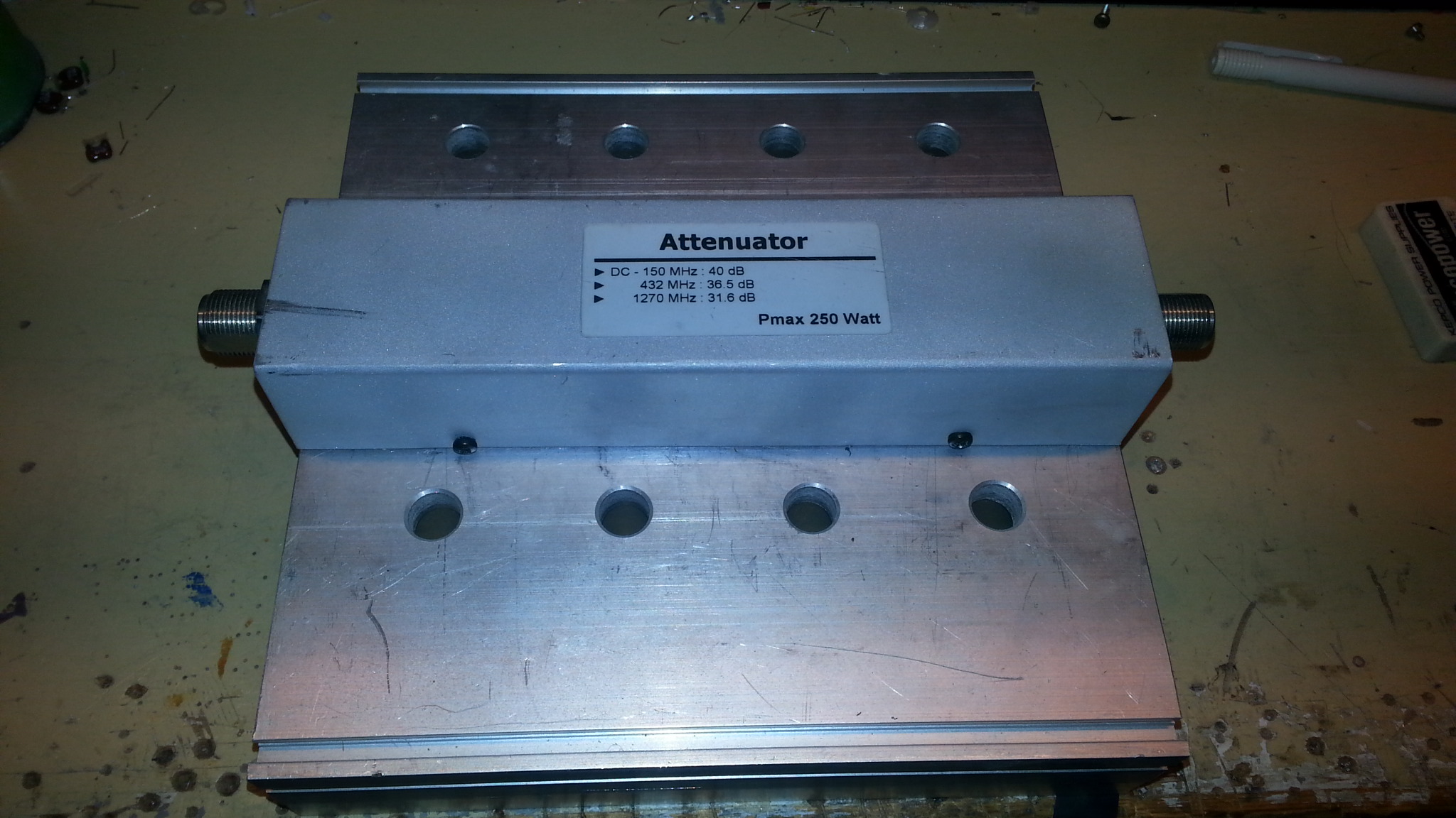
Measured values (with VNA) :
- DC-150 MHz : 40 dB
- 432 MHz : 36.5 dB
- 1270 MHz : 31.6 dB