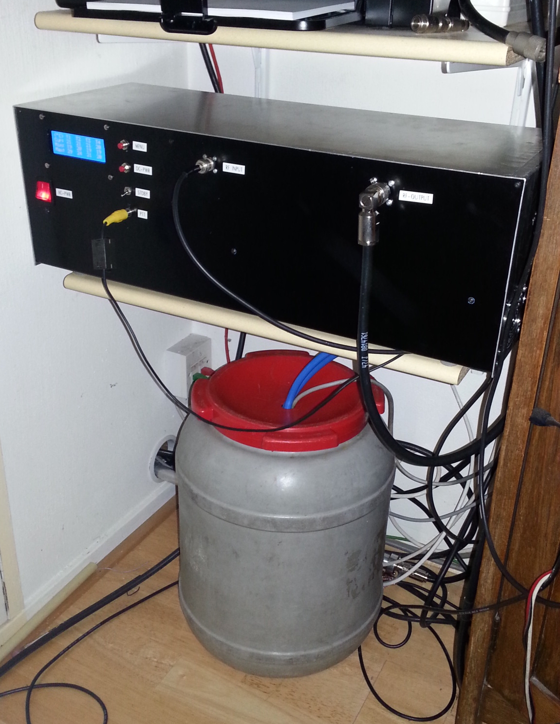
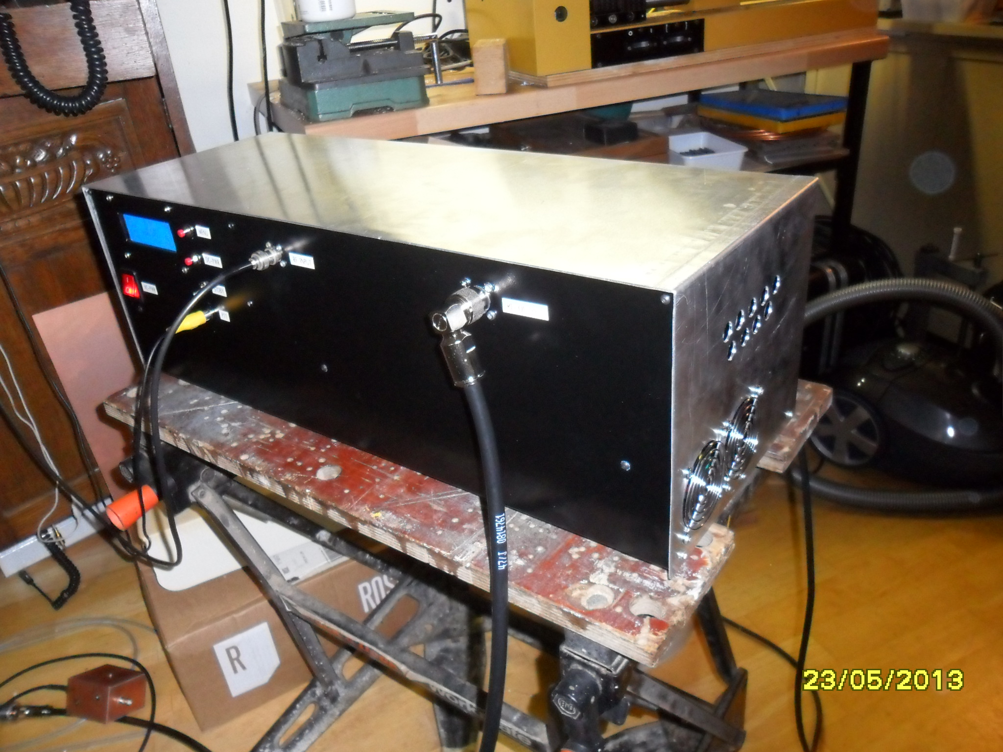
Finally my 144 MHZ QRO amplifier is ready. Based upon PCB of F1JRD and a BLF578 of NXP. The PA is capable of making > 800W but due to antenna limitations it can only run at about 400 Watt.

Power supply is a HP 50V / 60A unit originally used in a server, this is mounted with an auxiliary power supply (12V) on the bottom of the cabinet.
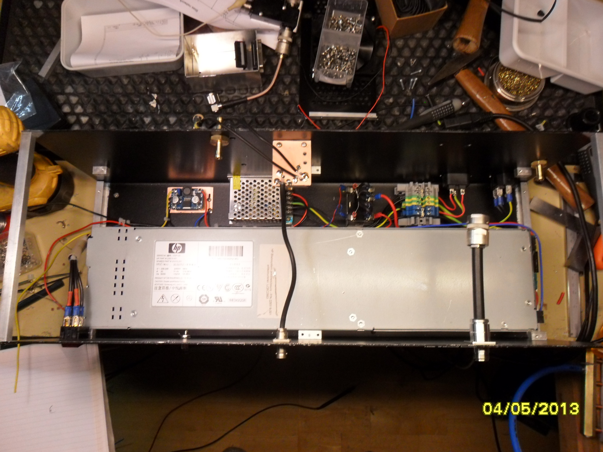
Some extra hardware is added to generate all voltages like a 50V–>28 Volt regulator. A high power relay is used to switch the 50V for the PA module.
The RF deck is mounted in the top half of the unit and contains the liquid cooled BLF578 pallet.


The liquid (water) is fed into the PA at the backside of the unit.


Here is also the 230V connection for the water pump, it will turn on directly when the PA is switched on through the main switch.
The RF deck contains two relays for in- and output switching, a home made measurement coupler (design from W1GHZ) with a pair of AD8307 log converters, a DC current meter (based up ACS713) and a homemade controller board (Arduino compatible).


To comply with the regulations, a high power low pass filter was added externally. Design can be found here, I slightly modified the lumped elements to have a better insertion loss.